Coordination
The Architecture of Time
How machines learned to measure cycles, divide frequencies, and keep promises.
TimersPrescalersPWMCompare MatchInput CaptureReal-Time Systems
1. The Illusion of Speed
In our earlier explorations, we watched systems learn to speak. UART established timing contracts, SPI synchronized clocks, and I2C/CAN introduced bus sharing. Yet, all communication protocols and computational structures share an underlying assumption: they assume the existence of structured, reliable time.
How does software wait? The most naive approach is a busy-wait delay loop:
for(volatile int i = 0; i < 100000; i++);
This simple loop runs on a test bench, but collapses in a real-world system. First, it is entirely clock-frequency dependent: if the microcontroller switches from an 8 MHz internal RC oscillator to a 168 MHz external crystal, the delay shrinks to a fraction of its intended duration. Second, if you enable compiler optimizations (such as -O3), the compiler may strip the empty loop entirely. Third, if an interrupt service routine (ISR) fires during the loop, the CPU suspends execution to handle the event, stretching the delay unpredictably. Software alone cannot keep temporal promises.
2. The Hardware Counter
To keep time reliably, the CPU must delegate the task to dedicated hardware: the timer. At its simplest, a timer is an independent hardware block consisting of a clock oscillator feeding a digital register called the Counter (CNT).
On every tick of the clock, the counter register increments. Because this incrementing happens in hardware, it is completely independent of CPU execution. The CPU can be performing complex arithmetic, waiting for an interrupt, or even resting in a low-power sleep state; the hardware counter increments steadily in the background, counting clock cycles to track elapsed time.
3. Prescalers: Division of Labor
Directly clocking the counter register quickly reveals a physical limitation: frequency. Suppose our microcontroller runs at 84 MHz, and we use a 16-bit counter register (which can hold values from 0 to 65,535).
At 84 million ticks per second, the counter will fill up and wrap back to zero in just 780 microseconds. Measuring a simple 1-second interval would require tracking thousands of wraps in software, consuming CPU cycles and defeating the purpose of hardware timing.
To solve this, timers use a Prescaler (PSC). The prescaler is a programmable frequency divider. If we set the prescaler to 8399, the incoming 84 MHz clock is divided by 8400 (PSC + 1), feeding the counter a slow, manageable 10 kHz signal. The counter now increments once every 100 microseconds, wrapping in a comfortable 6.5 seconds.
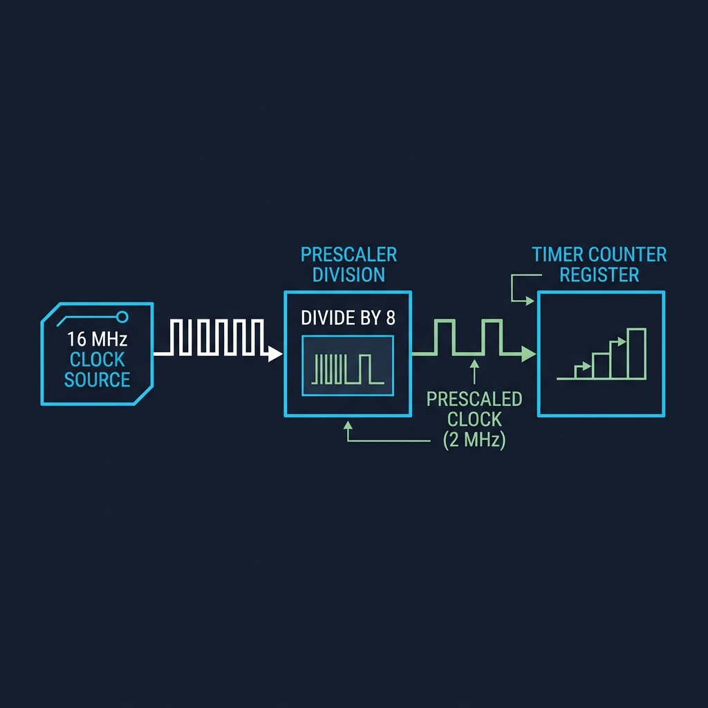
Timer Clock Division: Clock source divided by Prescaler to drive Counter CNT
4. Overflow: The Heartbeat of wrapping
When the counter register counts past its maximum value (or a configured Auto-Reload Register / ARR value), it wraps back to zero. This wraparound is called an Overflow.
The moment an overflow occurs, the timer hardware asserts an Update Interrupt Flag (UIF) and can trigger a CPU interrupt. By adjusting the ARR value, we dictate the exact period of this wraparound. A 10 kHz counter configured to wrap at 10,000 generates an overflow interrupt exactly once every second, creating a deterministic periodic heartbeat.
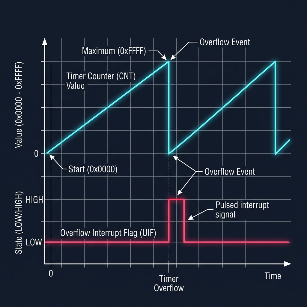
Timer Overflow Sequence showing Counter wrapping at ARR and generating Update Flag
5. Compare Match: Keeping Promises
Periodic overflows are useful, but what if we need events to happen during the count cycle? That is where the Compare Register (CCR) comes in.
The CPU writes a target value to the CCR. The timer's hardware comparator continuously checks: Is CNT == CCR?.
The moment the counter matches the compare register, the timer asserts a Compare Match flag and can toggle an output pin or trigger an event. This allows the system to schedule precise sub-millisecond events without CPU intervention.
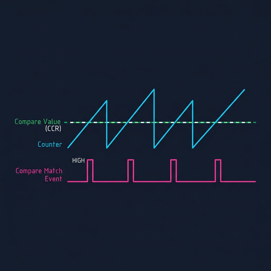
Timer Compare Match Waveform showing Counter intersecting CCR to trigger Match Events
6. Timer Configurator: The Race Against Time
Let's experiment with these core concepts. In the simulator below, configure the clock source, prescaler division, counter size, and compare match values to see how physical frequencies translate into structured temporal events.
7. Pulse Width Modulation: Painting with Time
Compare match logic unlocks a powerful technique: Pulse Width Modulation (PWM). If we configure a timer pin to go HIGH on counter reset (0) and go LOW when the counter matches the Compare Value (CCR), we generate a repeating digital pulse train.
By changing the compare value, we adjust the Duty Cycle—the percentage of the period that the signal is HIGH. By toggling this signal at high frequencies, we can simulate an analog voltage.
A 50% duty cycle on a 3.3V pin outputs 3.3V half the time, averaging to 1.65V. To an LED, this appears as half brightness. To a DC motor, it translates to half speed. Timers allow us to paint analog behaviors onto digital silicon using nothing but time.
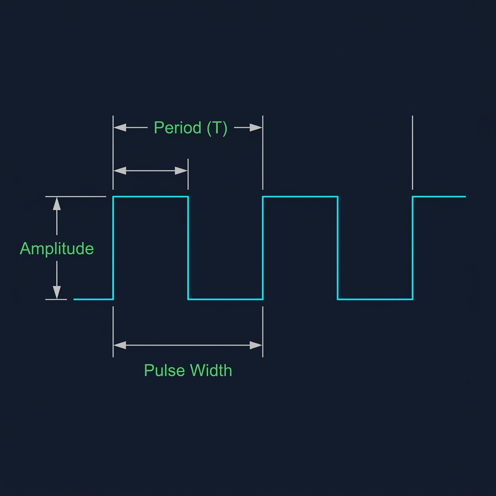
PWM Waveform showing Period, Pulse Width, and Amplitude
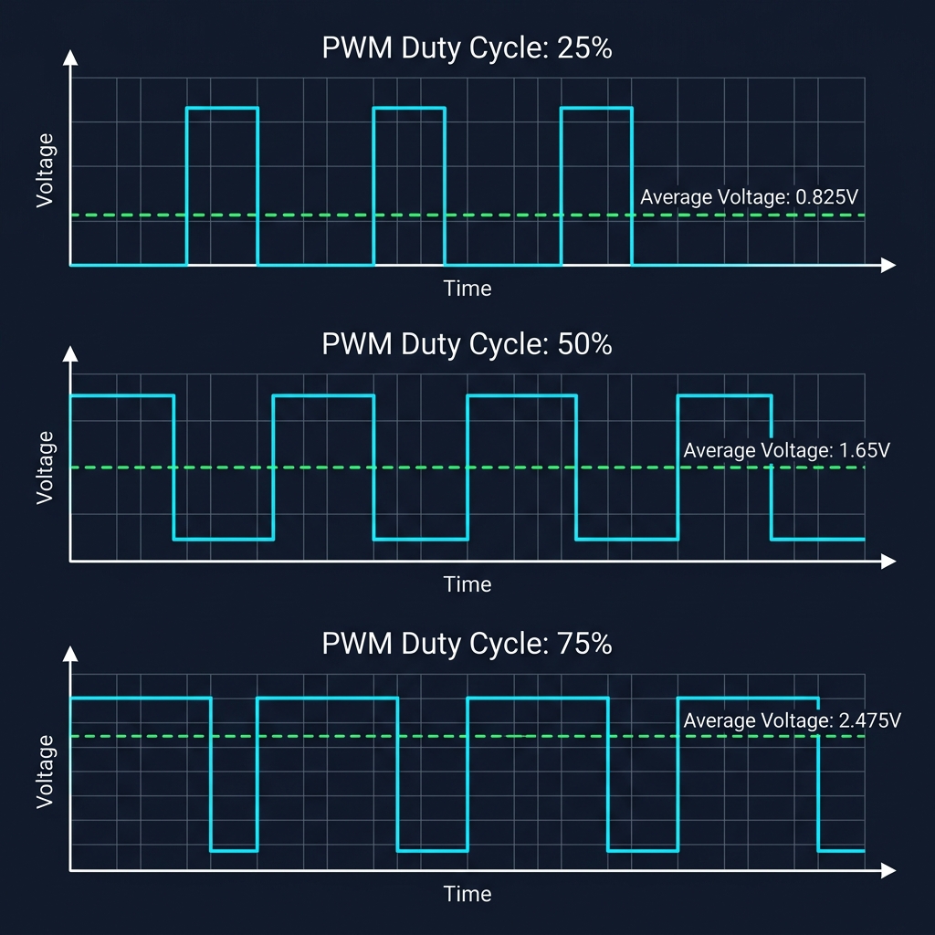
Comparison of 25%, 50%, and 75% Duty Cycles and resulting average voltages
8. PWM Simulator: Painting with Time
Adjust the frequency and duty cycle below to see how pulse widths map directly to average output voltages, controlling LED intensity and motor velocity.
9. Input Capture: Measuring the World
Timers do not just generate waveforms; they can also measure them. This is the role of Input Capture.
Instead of the counter triggering changes on an external pin, external pin transitions (edges) trigger the timer. When a rising edge is detected on an input capture pin, the hardware instantly copies (captures) the current counter value (CNT) into the capture register (CCR). When the falling edge arrives, it captures the value again.
By subtracting the first captured value from the second, the software can measure the exact pulse width of an external signal down to the nanosecond, enabling precise sensor decoding (such as ultrasonic distance sensors or RPM tachometers) with zero CPU polling overhead.
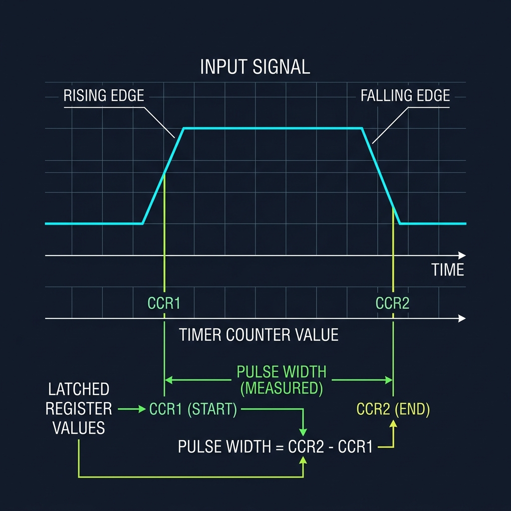
Timer Input Capture timing showing CCR latching at rising/falling edges to measure width
The Foundation of Decision
Communication protocols taught machines how to exchange information. Time taught machines how to coordinate action.
Before a system can observe the world, react to events, or schedule complex work, it must first learn how to measure time itself. With a structured heartbeat established, we can begin exploring how multiple activities are coordinated on a single CPU core.
Time is the canvas upon which coordination is painted. Without a clock, a machine is merely reactive; with one, it becomes purposeful.
Current Exploration
The Architecture of Time
