Computation
The First Instruction
The hidden journey from power-on to main().
FirmwareHardwareBootloaderSystems Architecture
1. The Myth of main()
To the software engineer working with high-level languages, the universe begins with a simple declaration: int main(). It is the clean boundary where our code begins to run, the genesis of application state, and the first frame in our debugger. We write code under the comforting assumption that before main(), the processor is a blank canvas, waiting for our instructions to bring it to life.
But this is a convenient abstraction. In low-level systems, main() is not the beginning of the program; it is one of the final stages of a highly structured initialization sequence. Before the CPU ever executes the first instruction of your application, a complex choreography of physical and logical transitions must occur. Memory must be initialized, clock sources must stabilize, interrupt lines must be routed, and the execution environment must be built out of raw silicon.
If firmware already exists inside non-volatile memory, how does it actually come alive? How does a block of inanimate code become a dynamic, executing system? To answer this, we must look before the beginning.
main() is not the beginning of firmware. It is the point at which the system finally hands control to the developer.
2. Power-On: The Silent Beginning
Before computation can occur, the physical environment must stabilize. When power is first applied to a microcontroller, the system undergoes an analog transition. The power rails do not instantly reach their nominal operating voltages; they climb along a capacitive ramp governed by the power supply circuitry.
During this brief startup ramp, the voltage levels are insufficient to toggle digital logic gates predictably. If the CPU began fetching instructions immediately, it would read corrupted bytes, registers would settle into random states, and the system would crash. To prevent this, microcontrollers incorporate specialized supervisor circuitry—typically a hardware Reset circuit paired with Brownout Detection (BOD).
The Brownout Detection circuit acts as an analog sentinel. It holds the CPU's internal reset line low, forcing all digital registers and execution pipelines into safe, defined hardware default states. While the reset line is active, the system's main crystal oscillator is powered up. The oscillator requires time to stabilize, moving from thermal noise to a steady, rhythmic sine wave.
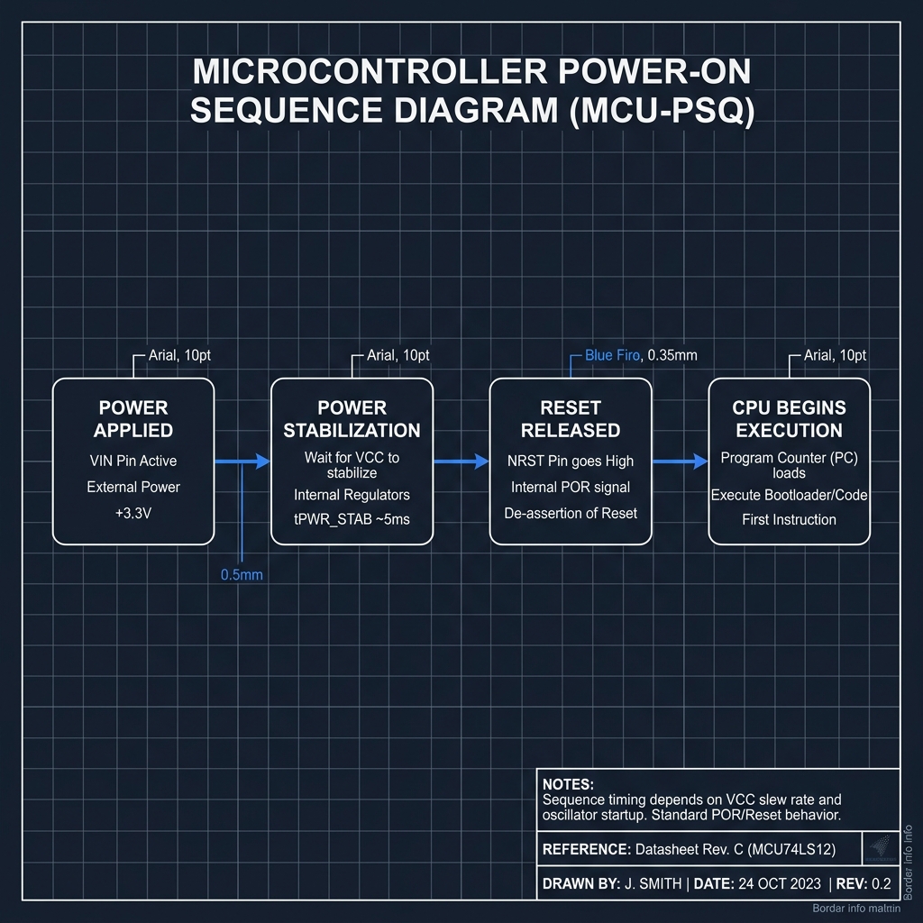
Power-On Sequence
The progression from raw electrical power application to voltage stabilization, reset release, and the birth of instruction execution.
Once the power supervisor detects that the supply voltage has crossed a safe threshold and remains stable, and the oscillator has settled into a steady rhythm, the hardware reset signal is finally released. Only now, with stable power and a reliable clock pulse, can the processor take its first digital step.
3. The Reset Vector
When the reset line is released, the CPU's program counter does not start at a random location, nor does it scan the memory looking for code. Instead, the hardware is wired to look at a single, hardcoded address in the memory map: the Reset Vector.
This fixed startup address is a contract between the silicon designer and the systems architect. On 8-bit AVR microcontrollers, the reset vector is typically address 0x0000, where a jump instruction to the startup routine is placed. On 32-bit ARM Cortex-M processors, the CPU looks at address 0x00000000 to read the initial Stack Pointer, and then loads the address of the Reset Handler from 0x00000004 into the program counter.
Regardless of the specific architecture, the mechanism remains conceptual: the hardware reset release forces the CPU to load its very first instruction address from a dedicated slot. The reset vector is the gateway; it points the processor directly to the code that will build the software runtime.
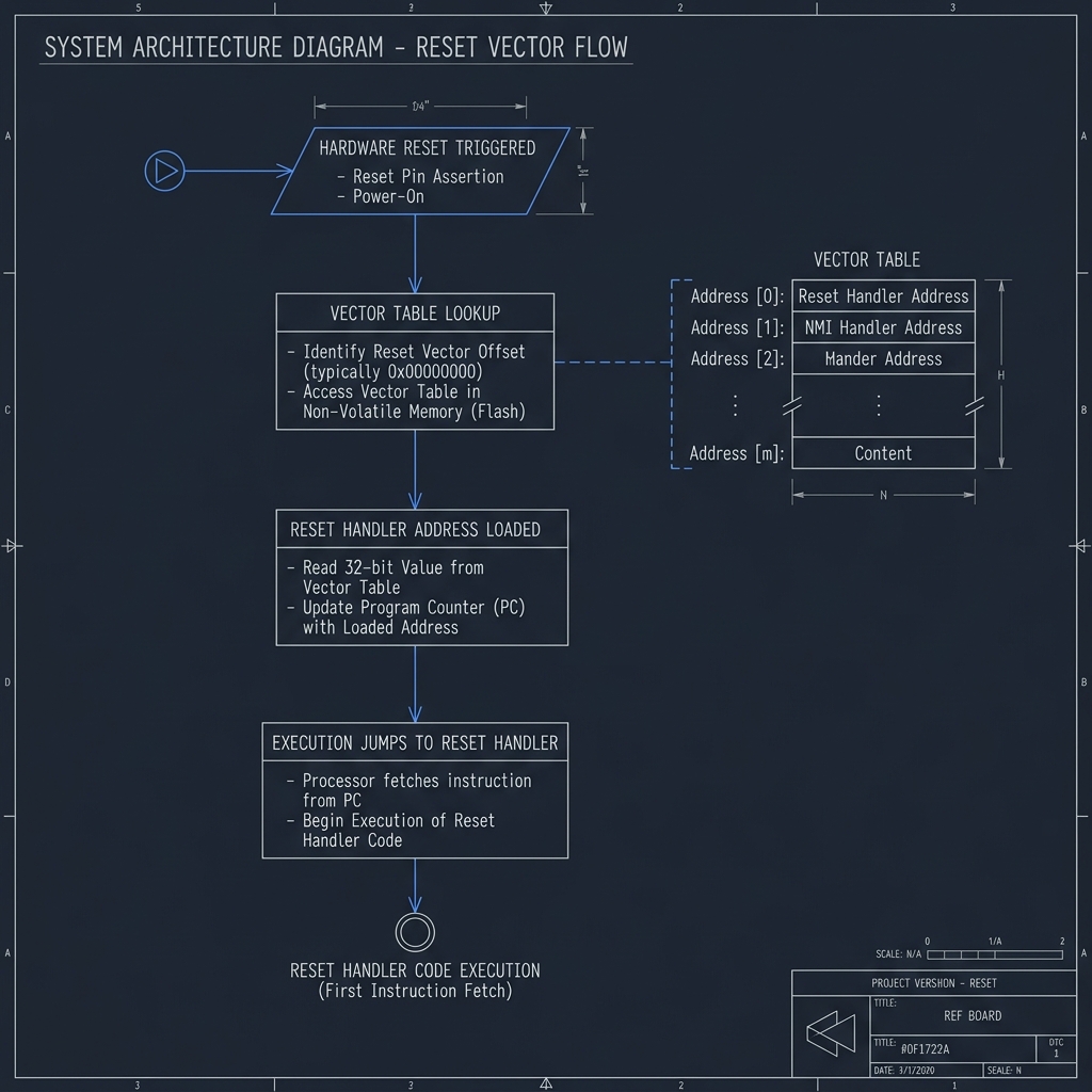
Reset Vector Flow
The deterministic path from physical reset release to loading the Reset Handler address from the vector table.
4. The Vector Table
Before a processor can execute complex software, it must know how to handle exceptions, faults, and interrupts. This mapping is defined by the Vector Table—the system's primary layout of execution targets.
The vector table is a sequential array of memory addresses located at the base of the executable address space (or relocated via a vector table offset register). Its entries do not contain instructions; they contain pointers to functions. The first few slots are reserved for critical system conditions: the initial Stack Pointer (so the CPU has a memory context for registers), the Reset Handler (where initialization code lives), the Non-Maskable Interrupt (NMI), and the HardFault handler.
Without this table, the CPU is blind to its own failures. If a memory access fault or illegal instruction occurs during early startup, the processor must instantly jump to a fault handler to prevent runaway execution. The vector table provides this safety net before any user code can run.
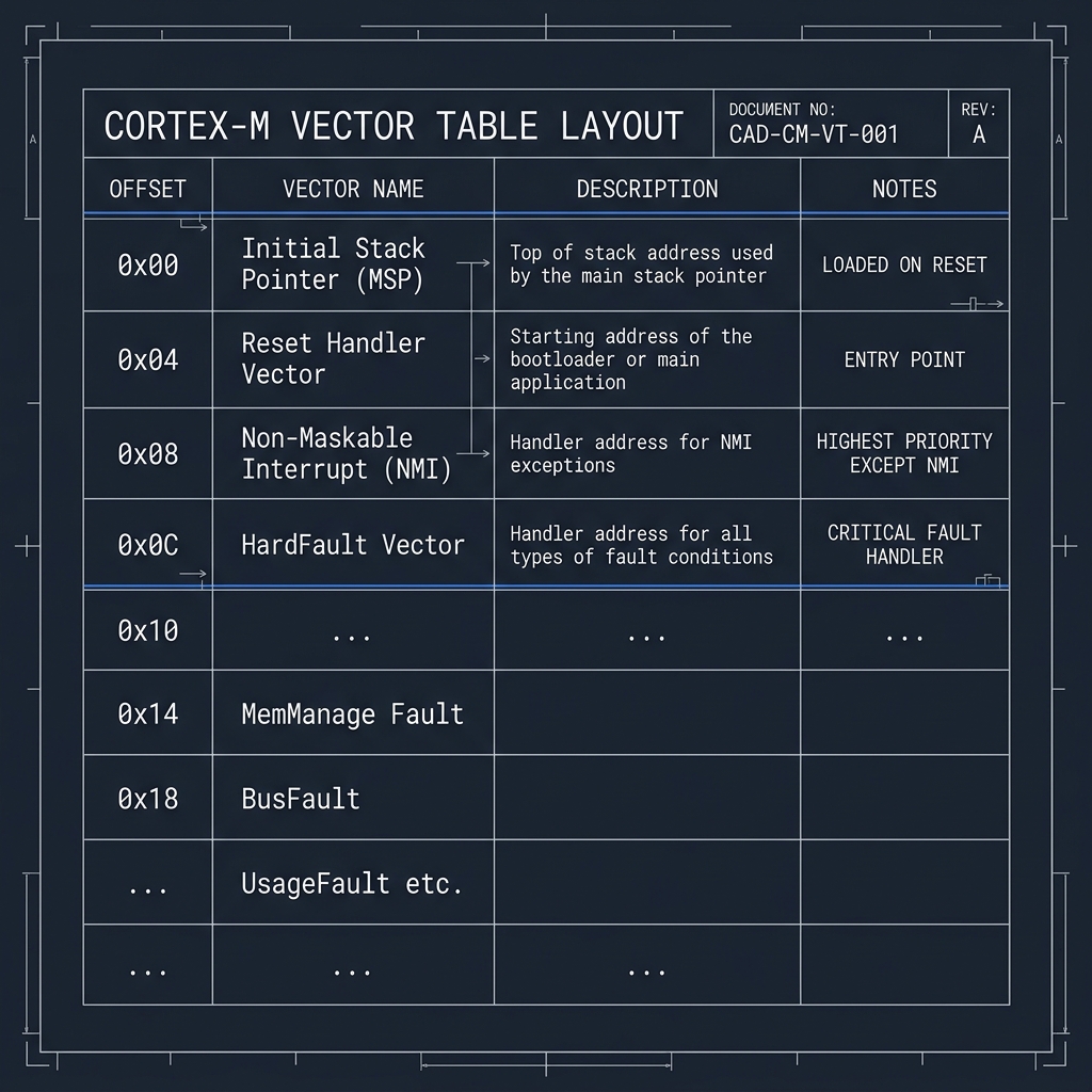
Cortex-M Vector Table
The layout of the vector table, mapping system exceptions and hardware faults to their handler addresses.
5. The Startup Code
Having loaded the address of the Reset Handler, the CPU begins executing the startup code—typically written in assembly or highly optimized bare-metal C. The primary objective of this phase is memory migration, bridging the gap between persistent storage and volatile workspace.
As explored in 'The Hidden Geography of Firmware', global and static variables are split into different sections. At boot, RAM contains nothing but volatile electrical noise. However, global variables in the '.data' section must start with their defined, non-zero values. Since RAM cannot hold this state across power cycles, these initial values are stored in Flash.
The startup code performs a literal copy loop: it reads the initialization values from Flash and writes them to their corresponding RAM addresses. Next, it zeros out the '.bss' section in RAM, ensuring all uninitialized global variables are clean. Only when this migration is complete is the system's memory model aligned with the developer's expectations.
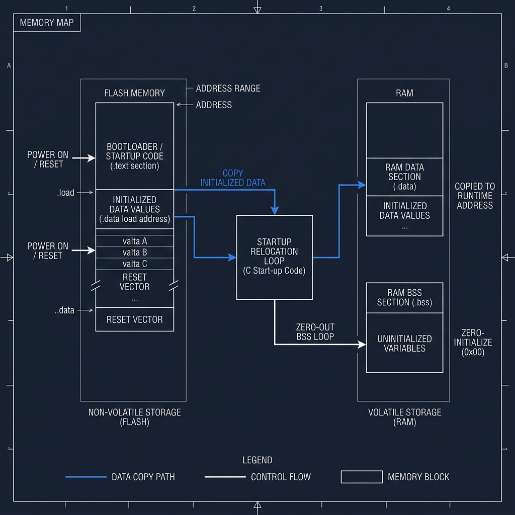
Startup Memory Initialization
The startup copy routine migrating initialized data from persistent Flash to volatile RAM and zeroing out the BSS segment.
6. The Clock Awakens
At boot, the microcontroller operates on a slow, low-power internal RC oscillator. This default clock source requires no external components and starts up instantly, but it lacks the precision and speed needed for high-performance computation or high-speed communication.
Once memory is initialized, the system must establish its operational rhythm. The startup code configures the clock tree: it enables the external crystal oscillator (which takes several milliseconds to stabilize), waits for it to lock, and then engages the Phase-Locked Loop (PLL) circuits to multiply the base frequency up to the system's target operating speed.
This transition requires care. The flash memory access latency (wait states) must be adjusted to match the new speed; otherwise, the CPU would fetch instructions faster than the Flash could supply them, causing a system crash. Once the clock tree is stable, the system switches its core clock source to the PLL output, and the processor begins running at full speed.
A processor without a clock is a mind without rhythm.
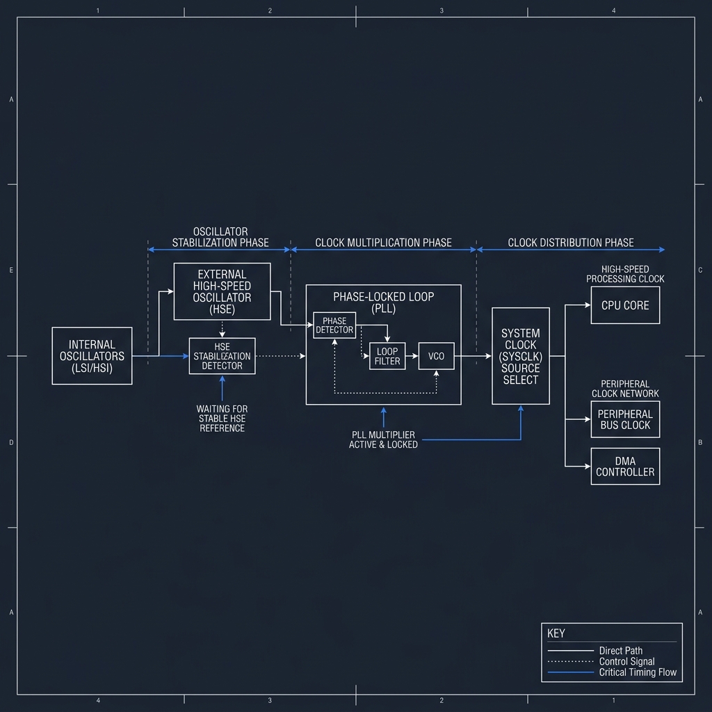
Clock Startup Chain
The clock propagation path from the base oscillator through frequency multiplication to core system clock distribution.
7. Bootloaders: The Gatekeepers
In simple microcontrollers, the reset vector points directly to the startup code of the main application. But in modern, production-grade systems, execution rarely jumps straight to user code. Instead, the CPU passes through one or more bootloaders.
A ROM bootloader—sometimes called a primary bootloader—is burned into the processor's silicon during manufacturing. It is immutable. At boot, it executes first, checking GPIO pins or memory flags to decide if it should enter a firmware update mode (pulling new code over UART, USB, or CAN) or hand off control to a secondary bootloader.
The secondary bootloader lives in flash memory and provides custom system logic. It might manage dual-image bank switching for safe OTA updates, initialize external RAM, or verify the integrity of the application firmware before jumping to its entry point.
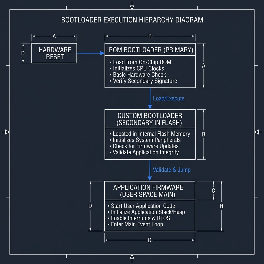
Bootloader Hierarchy
The execution flow passing through ROM and custom bootloader stages before reaching application firmware.
By separating the boot process into layers, the system gains robustness. If the main application becomes corrupted during a flash write, the bootloader remains intact, providing a recovery path that prevents the device from becoming permanently unresponsive.
8. Secure Boot and Trust
In an interconnected world, the boot process is not just about functionality; it is about security. Secure Boot establishes a chain of trust that guarantees only authentic, unmodified code can run on the hardware.
This chain begins with a Root of Trust—typically a public key hashed into read-only memory or one-time programmable (OTP) fuses inside the CPU during manufacturing. The immutable ROM bootloader uses this key to cryptographically verify the signature of the next boot stage. If the signature matches and the code is verified, the ROM bootloader executes it.
This verified stage then repeats the process for the next layer, validating the application firmware binary before handing over control. If any link in this chain fails—due to a corrupted download, a tampering attempt, or an unauthorized firmware image—the boot process halts immediately.
Modern systems no longer ask only whether firmware exists. They ask whether it deserves to execute.
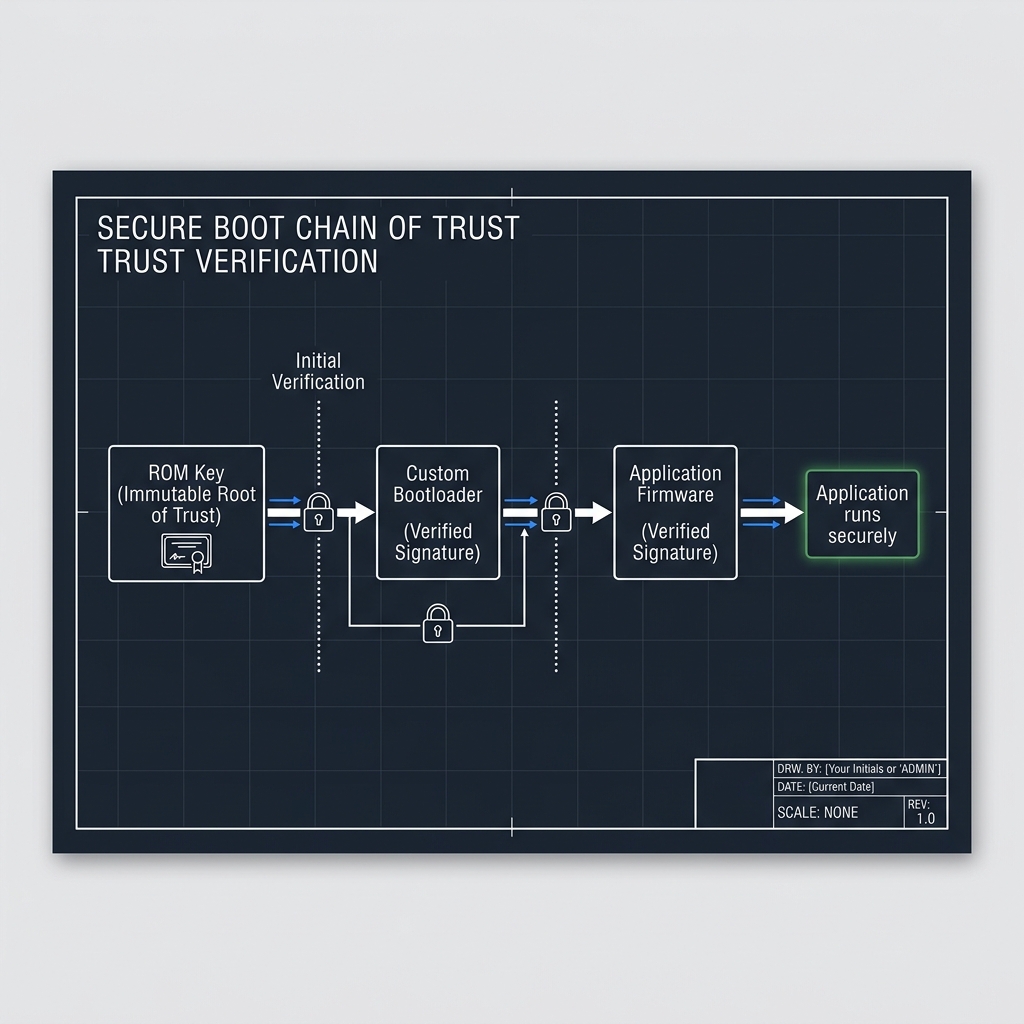
Secure Boot Chain of Trust
The sequential validation of signatures from the hardware Root of Trust down to the application layer.
9. The Handoff
After passing through electrical stabilization, vector loading, memory relocation, clock configuration, bootloader checks, and cryptographic verification, the system is finally ready. The runtime environment is fully realized.
The processor is running at its full frequency. Volatile memory is partitioned and initialized. The stack is clean, the heap is ready, and the interrupt system is armed. The startup routine performs the final handoff: it loads the address of the main() function into the program counter register.
At this exact moment, control shifts. The invisible machinery that brought the machine from inert silicon to an executing system recedes into the background. The first line of your main() function executes.
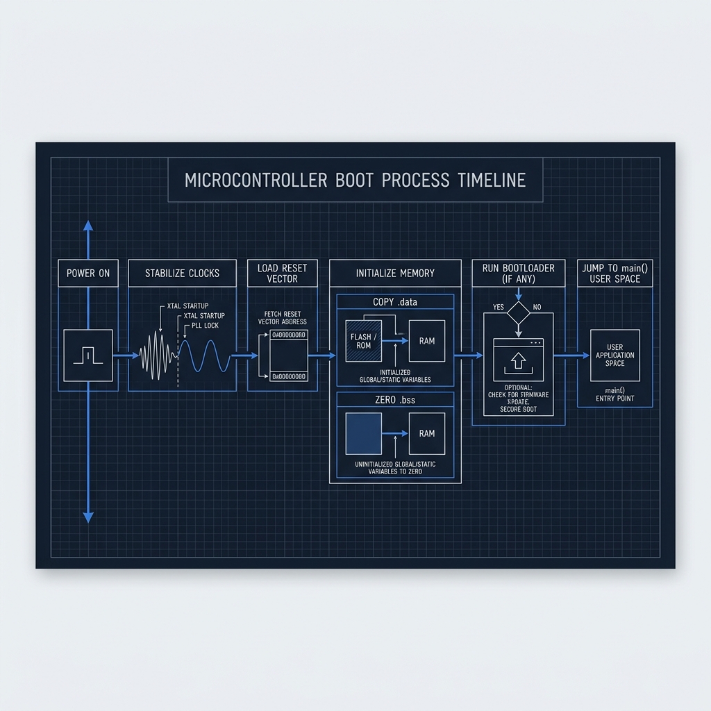
Complete Boot Process Overview
The entire architectural sequence from physical power-on to main() execution.
The Invisible Journey
Every firmware project hides an invisible journey. Before a single application instruction executes, an entire chain of hardware, memory, startup logic, and trust decisions has already occurred.
The developer sees main(). The system experiences a much longer story.
The first instruction is rarely the one written by the developer. It is the one that teaches the machine how to become itself.
Current Exploration
The First Instruction
